Developing a Functional Circuit Test System Using LabVIEW and PXI
 “By developing our new FCT system with PXI and LabVIEW, we greatly reduced duplication of engineering effort and can more easily share resources. We successfully applied this solution to our production lines, resulting in stable and reliable PCB testing.”
– Wei Wang, Honeywell Co. Ltd, China Company
The Challenge:
Testing audio/video circuits and static parameters for printed circuit boards (PCBs) on the manufacturing line while avoiding high engineering time and cost when target products change.
The Solution:
Developing a flexible, easy-to-use function circuit test (FCT) system using PXI and NI LabVIEW and cutting test system costs in half.
Batch-manufactured PCBs must pass both in-circuit tests (ICT) and FCTs before leaving the factory. ICT is usually the first test step in which every electronic component is tested and every short and open fault of every circuit are checked online. Most PCBs use firmware to control the integrated circuit board.
After the ICT, we can judge the quality of electronic components and parts for the PCBs in question, but we cannot determine whether the whole circuit functions properly or not. Test engineers must build an analog circuit environment to conduct FCTs on test point (TP) on an integrated circuit board. The FCT simulates the functions of finished products and tests if those functions complete.
In most cases, FCT systems on the production line only test one type of PCB. Such systems are generally developed by designing the control boards and connecting all the I/O ports to the test fixture. Then test engineers build the firmware for the control board to set up the simulated operating ambient of the finished products to test voltage and current as well as the corresponding sequential control. After testing is complete and products leave the factory, the FCT system is often shelved, and FCT systems developed for different PCBs require additional engineering resources for plate making, programming, and wiring. In addition, more complex functions are constantly added to PCBs, which makes some functional testing more difficult to build.
Honeywell wanted to avoid duplicating effort that was often the result of this development process and identify a lower-cost, more flexible solution that could address FCTs of multiple PCB products and the growing complexity of PCB functionality.
Using the PXI hardware platform and LabVIEW software, Honeywell focused on creating a complete set of comprehensive automatic function testing to test audio, video, and various signals such as voltage, current, and digital.
Functionality Requirements
Honeywell prioritized the following test functions:
- Multiple high-speed bidirectional I/O that monitors the state of the fixture and realizes communication protocols such as I2C to implement the sequential control of most chips on the PCBs
- Multiple analog input and output channels that can generate waveform signals as the simulated inputs for the PCBs
- Multichannel programmable switch matrix for on-off control
- RS232, RS485 serial port card to realize serial communication
- Programmable multimeter for voltage and current measurement
- Oscillograph for frequency measurement and waveform acquisition
- Video generation, acquisition, and analysis
- Audio acquisition and analysis
- Programmable power module
- Unified programming environment
Using traditional instruments to achieve this level of functionality would require prohibitively high costs. Implementing the NI solution with PXI and LabVIEW helped us achieve our goals and cut costs by half.
System Architecture
In the past, a test fixture was necessary for a simple FCT system. Different functional requirements demanded design of various control circuits, which are wired to the dial base. In addition, the firmware for a single-chip microcomputer needed to be programmed. Test results were displayed on the LCD; for more complex systems, PC software was developed to control the serial communication between the single-chip microcomputer and PC. Using PXI, Honeywell’s solution freed up test engineers who avoided duplicating efforts in plate making, programming, and wiring.
The advantages of the PXI and LabVIEW solution include the following:
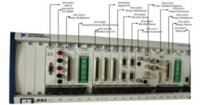
Unified allocation of hardware resources: Using the 18-slot NI PXI-1045 3U chassis, we can easily allocate hardware resources according to the slot number of various cards. By using the small computer system interface (SCSI) cable, signals are wired to the flank of the device called the “interface receiver.”
Unified interface of test fixture: A fixed-size neilsbed pedestal is located on top of the “interface receiver.” TP signals are wired through the pedestal interface to PXI acquisition modules.
Programmable power control: By controlling the programmable power module with GPIB, a steady supply of any voltage and current within the working range can be generated to various kinds of PCBs.
Unified control software interface: LabVIEW provides a unified user interface and modular programming with each PXI module, which results in shorter programming time.
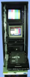
Reasonable layout of machine cabinet: PXI allowed for a simple and compact layout of all the instruments in the system. We implemented a 2 by 1.2 by 1.4 m machine cabinet with five layers.
Lower-Cost Audio Testing
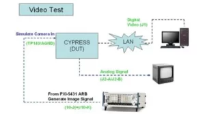
Audio tests are essential to the electronic security products. The audio quality of many products must meet high national standards. The NI PXI-4461 data acquisition module can completely replace a more expensive audio analyzer. Combined with NI software, the PXI-4461 can acquire and analyze audio signals and simulate a sine signal as an input source to PCBs, and measure the frequency and amplitude of the audio output signal.
System Software Design
The efficiency of the FCT system could only be fully realized when the hardware was combined with easy-to-use software. The seamless integration of LabVIEW with PXI was an obvious choice.
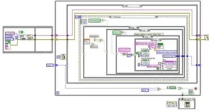
In addition, programming in LabVIEW allowed us to use various protocols such as GPIB, I2C, Modbus, and TCT/IP. In addition, by using the Virtual Instrument Software Architecture (VISA) library, we quickly and seamlessly implemented data processing and interactive display.
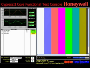
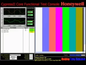
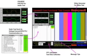
We divided the software’s front panel into five parts including the static parameter display window, audio test window, video test window, the percent of pass display window, and the information window.
Results
By implementing the FCT system using various PXI products and LabVIEW software, Honeywell achieved all test functionality requirements and realized accurate and rapid hardware control and high-speed acquisition. Even though the architecture of the FCT system is complex and has many inputs and outputs, it is powerful and easy to modify with the advantages of the PXI system. We can implement various kinds of FCT testing on PCBs without frequently replacing the test hardware. When new products are ready to test, we only need to replace the test fixture, connect the pins of the test fixture according to the hardware sources of the PXI system, and modify the corresponding test software. The LabVIEW graphical interface and ease of use allows test operators to simply activate the test fixture, operate according to the graphical tips of the host computer, and uplift the handle after the test is complete.
By developing our new FCT system with PXI and LabVIEW, we greatly reduced duplication of engineering effort and can more easily share resources. We successfully applied this solution to our production lines, resulting in stable and reliable PCB testing. When new products are released, the research engineers only need to add a new test fixture, allocate the probe, connect signals, and modify the software. The NI solution has greatly reduced Honeywell’s test engineers’ workload and cut costs without sacrificing test quality or functionality.
Author Information:
Wei Wang
Honeywell Co. Ltd, China Company
China
